Build an AM Crystal Radio
A crystal radio, sometimes called a cat’s whisker radio, is one of the earliest radios ever built. It is capable of receiving AM Broadcast radio, and allows you to listen to the signal without even using a battery.
Though not a particularly practical radio design today, its simplicity makes for easy understanding and assembly. A crystal radio is still a popular diy radio project today.
Modern radios all incorporate some form of amplification to better hear these weak radio signals. The first of these radios with amplification were known as “transistor radios”, based on the device used to perform the amplification. If you would rather construct a transistor radio, see our AM transistor radio page.
Parts Required
I have also provided links to the parts I have used for convenience.
- Germanium diode (1N34A used in our example)
- High impedance earpiece
- Magnet wire for inductor
- Variable Capacitor, 50pF
- Loop antenna
- Solderless breadboard
AM Radio Basics
AM radio is short for “Amplitude Modulation”. AM radio uses a base “carrier frequency”, which is then adjusted or modulated by the signal it aims to carry (the data). For an AM radio station at 101.5 khz, for example, the carrier frequency is the 101.5 khz, and the voice signal sets the amplitude on the output signal.
A simple way to think about this is that the height peak in the carrier frequency represents the original value from our signal. This is the value we wish to separate from the combined incoming signal.
See our article on Amplitude Modulation for more details.
For more info on amplitude and signals, see our signals 101 article.
Basic Radio circuit
Any radio system needs at least at least three things:
- A resonant circuit to pick up the weak radio signal
- Signal processing, to select the data from the received signal
- An antenna
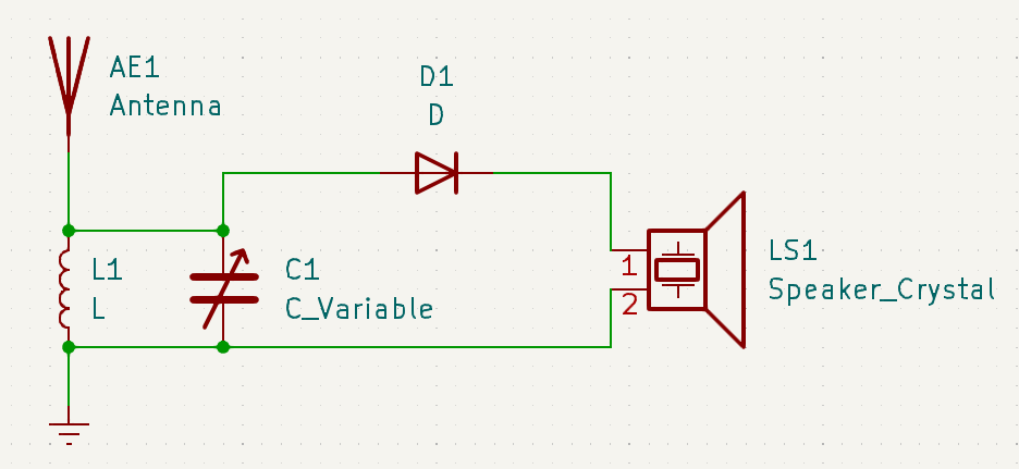
The LC Circuit.
The crystal radio makes use of an LC circuit to capture the incoming signal. The LC circuit consists of an inductor (a wrapped rod) and a capacitor. By selecting the values for these two components, we can design a circuit which resonates at a given carrier frequency, allowing us to pick up these weak signals.
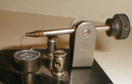
The inductor
We can build a solonoid inductor by wrapping insulated wire around a piece of iron or ferrite. See also ferrite rod antenna calculator.
Inductance (L) is measured in Henries. Our inductor will be about 1.78 milli henries or 1.78 mH.
For high inductance values, you can wrap wire around a metal rod to increase the inductance. If you find a suitable circular round item, you can use this for an “air core”.
Use the inductor calculator to help design an inductor with about 2mH of inductance.
The values I used:
- relative permeability: 200 (ferrite core)
- number of turns: 30
- cross sectional area: 1cm diameter \( \Rightarrow \pi * .5cm^2 = .785 cm^2 \)
- Resulting inductance: 1.78 mH
As you wrap the rod, you will want to go slowly, reducing the empty space between windings. Make sure you leave extra wire on both ends, so that we can easily plug our inductor into the rest of the circuit later.
The magnet wire is coated with a thin enamel coating to prevent it from making electrical contact along the sides. After you have wrapped your inductor, you’ll want to strip the casing off the tips of the wire.
If you prefer, you can also purchase an inductor with similar inductance.
The tuning capacitor
With our 1.78 mH inductor, and some yet undetermined capacitor, we would like the ability to tune to any station in the AM frequency range. In the US, this ranges from 540 Khz to 1700Khz.
We can plug these frequencies into the LC calculator to determine the capacitance values we’d need.
| Frequency | Capacitance |
|---|---|
| 540 Khz | 48.8 pF |
| 1700 Khz | 4.9 pF |
A single 50 pF variable capacitor can cover the entire range of values we need, from 0 to 50pF. This will let our radio cover the entire AM frequency spectrum.
The crystal detector
The fluctuating signal has peaks based on the data, but much of the waveform is from the higher frequency carrier. A crystal radio first “detects”, or rectifies the incoming signal. By discarding the negative parts of the wave, we have what resembles the data signal with some gaps.
Suppose the audio is just a constant tone around A440, at 440Hz. (see signals 101 for more details).
Lets suppose there were a station at 150 AM. This is lower than the lowest AM station in the US, but the lower frequency makes for clearer visuals. The incoming signal, consisting of the modulated 150 Khz carrier with the 440hz sound, would look like this (looking at only the first half of the period):
You can see how the overall shape takes on a much wider wave, and this is the 440 hz tone. The higher frequency wave inside is the 150 khz carrier signal.
After rectifying, it looks like:
The capacitor in the circuit will act to smooth between the peaks, resulting in an output sound that resembles the overall shape.
Why “Cat’s Whisker”?
Instead of a diode, early designs used a very thin wire touching a galena crystal. Visually, the thin wire looked a bit like a whisker on a cat.
(image from Wikipedia)
Galena is another name for lead sulfide. The wire and the crystal combined to create what is known as a P-N junction. The characteristics of these two metals results in a junction that allows current to flow only in one direction.
Modern diodes operate on the same principle.
The antenna
With a simple straight antenna, the radio waves are captured most effectively when the antenna length is ~1/2 of the signals wavelength.
We can use our wavelength calculator to determine the ideal antenna length.
| Frequency | Signal Wavelength (meters) |
|---|---|
| 540 Khz | 500 |
| 1700 Khz | 176 |
If you have space for such a large antenna, you are welcome to try it. Often, radio enthusiasts instead use a loop antenna. I have linked one at the top of the page.
Final Assembly
Now that we know what we’re building, lets put it together.
Note, with a solderless breadboard, connections are made between anything plugged into the same row. The only exception is the split in the middle. The two halves are not connected.
Row 1 will be used for ground.
Steps:
- Plug the white wire from the antenna into A1
- Plug the black wire from the antenna into A4
- Plug one wire from the inductor into B1.
- Plug the other wire from the inductor into B4.
- Install a wire from C1 to A4. Make sure to strip the insulation from the ends to enable an electrical contact.
- Install a 50pF capacitor between B4 and B6.
- Install a wire from A6 to C1 (ground).
- Install the diode. Unlike the previous components, the direction matters. There is a black marking on the diode which corresponds with the line in the circuit symbol. Plug this side into F4(right side).
- Plug the non-black side of the diode into E4(left side).
- Plug one end of the earpiece into G4.
- Plug the other end of the earpiece into D1.
Now your radio is fully assembled. Next we can slowly sweep across the capacitance range, searching for a station.
- Set the knob on the capacitors all the way to one side.
- Slowly turn the dial to the other side while listening with the earpiece. Feel free to stop when you find a station, or continue searching. If all went well, you should have been able to pick up some radio signals!
Conclusion
We hope you enjoyed building this radio. You have just experienced radio just as it was when it was first widespread.
Though this system can let you pick up AM radio broadcasts, the signal is often weak if you can find it at all.
The next step in the development of radio was to develop electronic amplification, to make it easier to hear these faint signals. In our next article, we’ll build a “transistor radio” which does just that.
If you have any feedback on this project, feel free to contact our team. We are always improving our projects, and any suggestions are greatly appreciated.